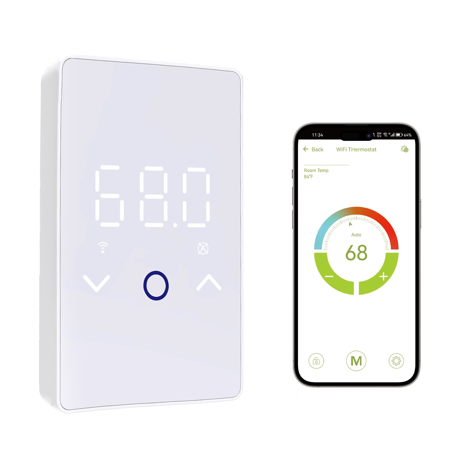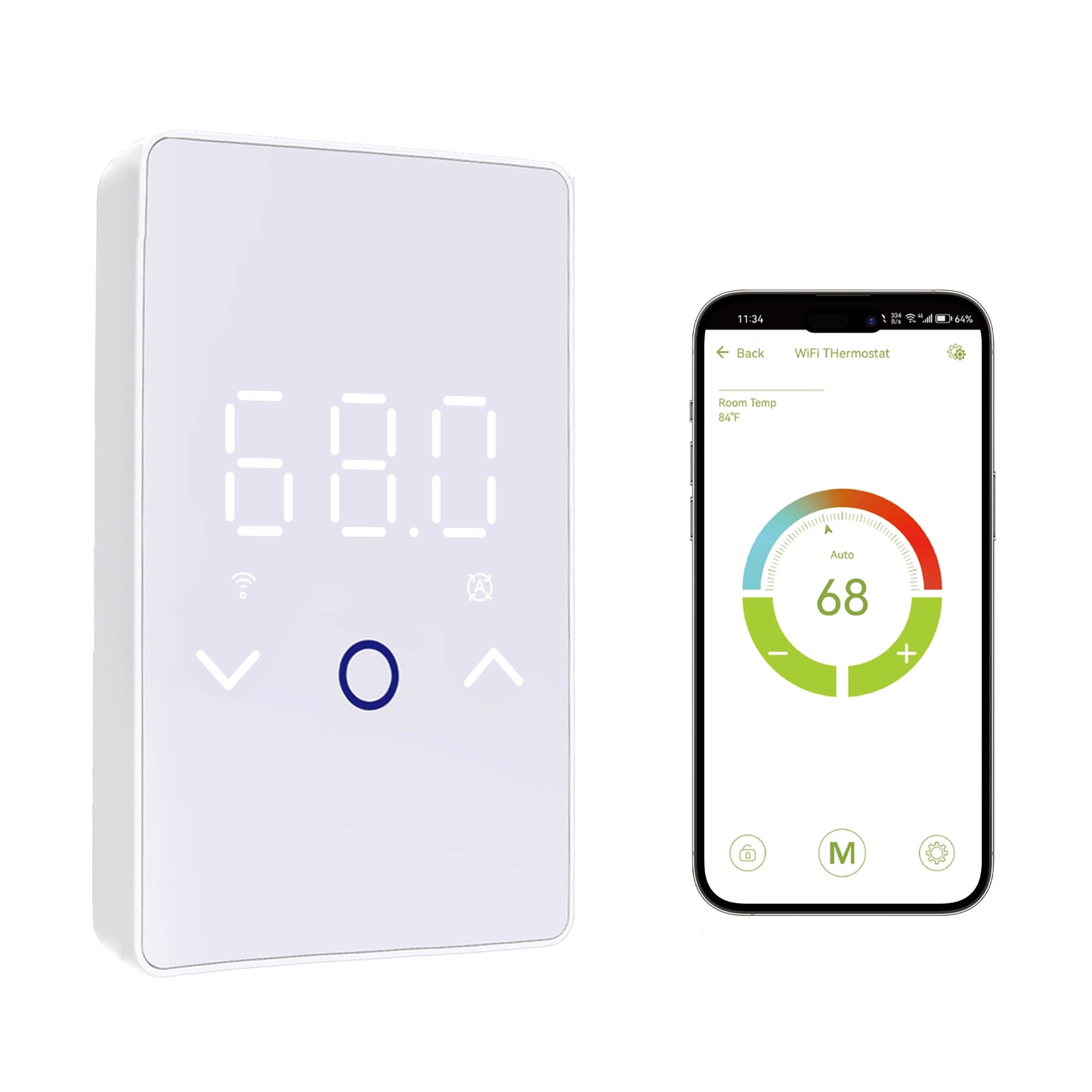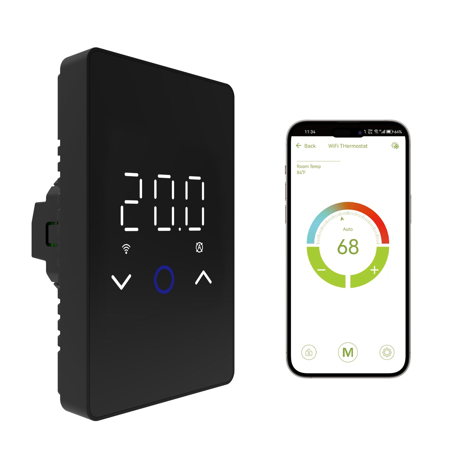
This MAXKOSKO smart thermostat installation guide explains what to verify before installing the ES29AW, how 120V and 240V floor-heating circuits affect wiring, where the floor sensor fits into the system, and how to connect the thermostat to the Smart Life App. Because the ES29AW controls line-voltage electric floor heating, electrical installation should be completed by a qualified electrician according to the product wiring diagram and applicable electrical codes.
Before Installing the MAXKOSKO Smart Thermostat
Do not begin by matching the wires from the old thermostat by color or terminal position.
First confirm that the ES29AW is compatible with the actual floor-heating system.
System Type
The ES29AW is designed for compatible resistive electric floor-heating cables and mats. It is not intended as a general HVAC, cooling, hydronic, wall-heater, or baseboard-heater controller.
Supply Voltage
Confirm whether the floor-heating system operates on 120V or 240V. The thermostat supports compatible systems at either voltage, but the wiring arrangement must match the actual circuit.
Total Heating Load
Add the current draw of every heating cable or mat controlled by the thermostat. The total connected resistive load must not exceed 15A.
Ground-Fault Protection
The ES29AW does not contain a built-in GFCI. The floor-heating circuit needs the ground-fault protection required by the applicable electrical code.
Line-Voltage Installation Requires Qualified Electrical Work
Turn off the circuit and verify that power is absent before installing, removing, or servicing the thermostat. A qualified electrician should identify the supply voltage, line and load conductors, grounding, circuit protection, wall-box wiring, and heating load before connections are made.
Do Not Exceed the ES29AW 15A Load Rating
The current ES29AW is rated for a maximum resistive heating load of 15A.
If multiple heating mats or cables are connected to one controller, their current draw must be added together.
Do not assume that a larger breaker allows the thermostat to control a larger load. The thermostat's own 15A rating still applies.
What If the Heating Load Is Over 15A?
A larger floor-heating installation may require separate thermostats or an appropriate relay, contactor, or power-control solution designed for the installation. Have a qualified electrician determine the correct circuit and control arrangement rather than exceeding the thermostat rating.
120V vs 240V Thermostat Wiring: Why the Difference Matters
The ES29AW can control compatible 120V and 240V electric floor-heating systems, but that does not mean both circuits use the same conductor arrangement.
In a typical North American 120V circuit, the supply commonly includes a hot conductor and neutral.
Many 240V floor-heating circuits instead use two hot conductors, commonly described as L1 and L2.
Because wiring methods and conductor identification can vary, do not determine the circuit only from wire color.
Do Not Copy the Old Thermostat Wiring Blindly
A replacement thermostat may use different terminal positions or labeling from the previous controller. The electrician should verify the actual supply, heating load, grounding, floor sensor, and voltage before following the ES29AW wiring diagram.
For this reason, this guide does not provide a generic color-to-terminal wiring recipe for every 120V and 240V installation.
Understand the Main Thermostat Connections
The ES29AW installation includes three different electrical functions:
| Connection Group | Purpose | What Must Be Verified |
|---|---|---|
| Supply | Provides line-voltage power to the thermostat. | Confirm actual 120V or 240V circuit configuration before wiring. |
| Heating Load | Connects the thermostat-controlled output to the compatible heating cable or mat. | Total connected resistive load must remain at or below 15A. |
| Floor Sensor | Provides temperature feedback from the floor assembly. | Use the included sensor for a new installation when possible, or verify compatibility before reusing an existing sensor. |
| Grounding | Provides the required equipment-grounding path for the floor-heating installation. | Follow the heating-system instructions and applicable electrical code. Do not omit required grounding. |
Use the Current Wiring Diagram
Terminal labeling and circuit configuration should be confirmed from the ES29AW instructions supplied with the thermostat. Do not rely on an older controller's terminal names as proof that the wiring functions are the same.
Install the Floor Sensor Before the Floor Is Closed
The ES29AW includes a dedicated external floor sensor, and using the matched sensor is the preferred approach for a new installation.
The sensor should be installed inside the heated floor area between adjacent heating-cable runs.
It should not:
- Touch the heating cable directly
- Cross over a heating cable
- Sit immediately beside a heating cable
- Be placed outside the area that is actually heated
- Be damaged while flooring materials are installed
If the sensor is installed too close to a heating cable, it can detect a locally warmer condition than the surrounding floor and affect thermostat control.
Consider Sensor Conduit During a New Installation
Where the floor-heating and construction instructions allow it, installing the sensor in appropriate conduit can make future sensor replacement easier. Follow the complete floor-heating installation instructions for routing and placement.
Replacing an Existing Thermostat? Check the Old Floor Sensor First
If the floor is already finished, replacing the embedded sensor may be difficult. In that situation, the existing sensor may be reusable—but only if it is compatible with the ES29AW.
The thermostat supports several selectable compatible sensor ranges, including:
- 0–10kΩ
- 1–10kΩ
- 2–12kΩ
- 3–15kΩ
The included ES29AW sensor is a 10k NTC sensor with B25/50 = 3380.
Do Not Select an Existing Sensor by Appearance
Two NTC sensors may look identical while using different resistance-temperature curves. A single resistance reading does not automatically prove full compatibility. Confirm the existing sensor specification before selecting a replacement-sensor setting.
If you are replacing an older controller and keeping the embedded sensor, read the floor sensor compatibility guide before replacing the thermostat.
Mount the Thermostat After Wiring Has Been Verified
Once the qualified installer has completed and checked the electrical connections, assemble the thermostat according to the product instructions.
Open the Thermostat Carefully
Use the designated lower opening point to separate the front assembly as directed by the thermostat instructions. Avoid forcing or twisting the touchscreen housing.
Secure the Back Plate
Mount the thermostat back plate securely to the compatible wall box while keeping conductors properly positioned and free from damaging pressure.
Reinstall the Front Assembly
Align the thermostat front with the mounted base and secure it according to the product instructions. Avoid applying unnecessary pressure directly to the center of the touchscreen.
If Room or Combined Sensor Mode will be used, thermostat location also affects the internal room-temperature reading.
Avoid locations strongly influenced by:
- Direct sunlight
- Localized hot or cold drafts
- Nearby heat-producing equipment
- Conditions that do not reasonably represent the room temperature
First Power-On: What Should Be Configured?
After wiring has been inspected and power can be safely restored, complete the initial thermostat configuration before depending on the heating system.
Confirm the Display Starts Normally
Check that the thermostat powers on without a persistent sensor error or other abnormal indication.
Select °F or °C
Choose the preferred temperature unit for normal operation and future troubleshooting.
Select the Correct Sensor Mode
Choose Floor, Room, or Combined control based on the floor-heating design and flooring requirements.
Confirm the Floor Sensor Type
If the included sensor is used, configure the thermostat accordingly. If an existing sensor is reused, confirm its compatibility before selecting its sensor setting.
Set Any Required Floor Limit
When the installation requires a maximum floor-temperature limit, use the flooring and heating-system instructions to determine the appropriate value. Do not use the thermostat's maximum available setting as the default.
For a complete explanation of the control logic, see Floor Sensor vs Room Sensor vs Both Mode.
How to Connect the ES29AW to Smart Life WiFi
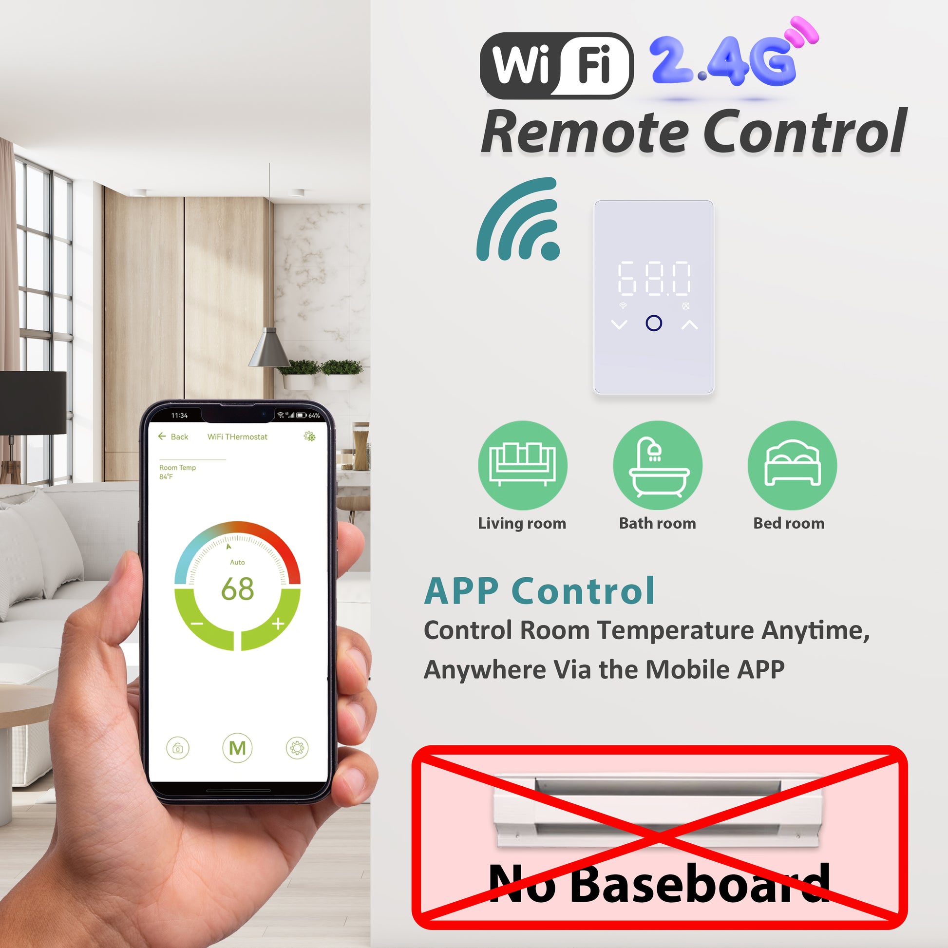
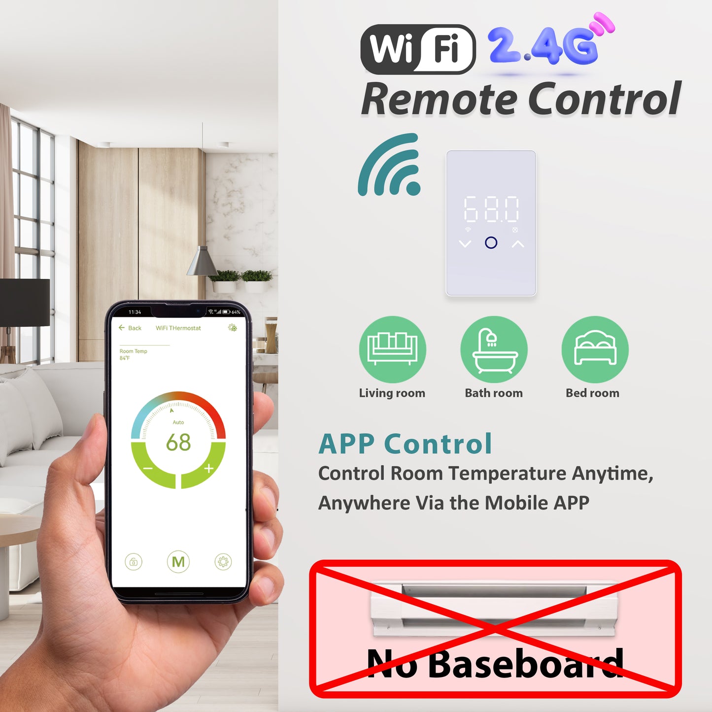
The thermostat can operate from its touchscreen without WiFi, but a compatible WiFi connection is required for Smart Life remote control and supported voice-assistant features.
Before Pairing
Prepare the following:
- A working 2.4GHz WiFi network
- A smartphone near the thermostat during pairing
- Bluetooth enabled on the phone
- The permissions requested by the Smart Life App
- The correct 2.4GHz WiFi password
- A stable WiFi signal at the thermostat location
5GHz-Only WiFi Is Not Supported for Pairing
If you use a dual-band router, make sure its 2.4GHz network is available during setup. The phone and thermostat need to complete the pairing process through the compatible network.
Smart Life Pairing: Step by Step
Install the Smart Life App
Download Smart Life from the appropriate app store for your phone and sign in or create an account.
Prepare the Thermostat for Pairing
Power the thermostat normally and check the WiFi indicator. The WiFi icon should be flashing rapidly when the thermostat is ready to pair.
Reset the WiFi Pairing State if Needed
If the WiFi icon is not flashing, press and hold the down-arrow control as directed for the ES29AW until the WiFi indicator enters the pairing state.
Add the Thermostat in Smart Life
Use the app's Add Device function and select the detected thermostat when it appears.
Enter the 2.4GHz WiFi Credentials
Provide the password for the compatible WiFi network and keep the phone near the thermostat while pairing completes.
Name the Thermostat
Use a practical device name such as “Bathroom Floor Heat” or “Kitchen Floor Heat” so the correct zone is easy to identify later.
What If Smart Life Cannot Find the Thermostat?
If the thermostat works from the touchscreen but will not connect to the app, troubleshoot the network side before changing electrical wiring.
Confirm 2.4GHz WiFi
Make sure the network being used for pairing supports 2.4GHz rather than being 5GHz-only.
Check Bluetooth and App Permissions
Bluetooth and the permissions requested by Smart Life can be needed during device discovery and pairing.
Check the WiFi Icon
Make sure the thermostat is actually in pairing mode. If necessary, reset the WiFi pairing state using the down-arrow control.
Move the Phone Closer
Keep the phone near the thermostat during initial setup and confirm that the thermostat location receives a stable wireless signal.
Check the Router
Confirm the 2.4GHz network is operating normally and retry the pairing process after resolving any router or password issue.
WiFi Failure Does Not Automatically Mean Heating Failure
The ES29AW can still be controlled locally from its touchscreen without WiFi. Loss of Smart Life connectivity should be separated from an electrical heating, sensor, or thermostat-control problem.
Do Not Turn the Installation Guide Into a Schedule Tutorial
Once the thermostat is installed, sensor mode is confirmed, and Smart Life is connected, the next step may be programming the weekly heating schedule.
The ES29AW supports:
- 5+1+1 scheduling
- Individual 7-Day scheduling
- Temporary manual adjustments
- Adaptive Heating
Those functions have their own setup logic, so use the dedicated ES29AW 7-Day schedule programming guide instead of changing installation settings just to adjust the weekly program.
If E1 or E2 Appears After Installation
An error code should be treated separately from WiFi pairing.
On the current ES29AW:
- E1 relates to the internal room-sensor circuit.
- E2 relates to the external floor-sensor circuit.
An E2 error after installation can be related to the floor-sensor connection, damaged sensor wiring, an incorrect sensor setting, or an incompatible reused sensor.
Do Not Bypass a Sensor to Make an Error Disappear
If a floor sensor or floor-temperature limit is required by the installed heating or flooring system, do not change modes simply to avoid an E2 warning. Find the cause of the sensor problem first.
Use the MAXKOSKO E1 and E2 troubleshooting guide for the full diagnostic sequence.
Common ES29AW Installation Mistakes to Avoid
Assuming 120V and 240V Wiring Is Identical
The thermostat supports both voltages, but the actual supply conductors and circuit configuration must be identified before wiring.
Exceeding 15A
Adding multiple heating mats does not increase the thermostat's current rating. Calculate the combined heating load before installation.
Assuming GFCI Is Built In
The current ES29AW does not contain built-in GFCI protection. Required ground-fault protection must be provided elsewhere in the circuit.
Poor Floor Sensor Placement
A sensor touching a heating cable or positioned outside the heated area can produce misleading temperature control.
Guessing the Existing Sensor Type
Do not assume an embedded sensor is compatible simply because its wires or resistance look similar to the supplied sensor.
Treating WiFi as Required for Basic Heating
Smart Life provides remote features, but local thermostat control remains available from the touchscreen.
When to Stop and Call a Qualified Electrician
Professional Evaluation Is Appropriate If:
- You cannot positively identify whether the circuit is 120V or 240V.
- The existing wiring does not match the current thermostat instructions.
- The combined heating load may exceed 15A.
- Required ground-fault protection is missing or unclear.
- There are burned, melted, discolored, or damaged conductors or terminals.
- The breaker or ground-fault device repeatedly trips.
- The floor sensor wiring is damaged or inaccessible.
- A persistent E1 or E2 error remains after the relevant checks.
- Line-voltage measurements or circuit modifications are required.
Do not bypass the breaker, ground-fault protection, floor sensor, thermostat, or other required protection to force the floor-heating system to operate.
MAXKOSKO ES29AW Installation Checklist
- Confirm the thermostat is being used with a compatible electric floor-heating cable or mat.
- Verify whether the actual circuit is 120V or 240V before wiring.
- Do not copy old thermostat wiring by color or terminal position alone.
- Keep the total connected resistive heating load at or below 15A.
- Provide the ground-fault protection required by applicable electrical code because the ES29AW does not have built-in GFCI.
- Install the floor sensor between heating-cable runs without touching or crossing the heating cable.
- Verify an existing embedded sensor before reusing it with a replacement thermostat.
- Select the correct Floor, Room, or Combined control mode during initial setup.
- Use 2.4GHz WiFi, Bluetooth, and Smart Life for remote pairing.
- Remember that basic touchscreen control remains available even without WiFi.
- Use the dedicated schedule, sensor-mode, and E1/E2 guides for deeper setup or troubleshooting.
Installing or Replacing an Electric Floor Heating Thermostat?
The MAXKOSKO ES29AW Smart WiFi Thermostat is designed for compatible 120V and 240V electric floor-heating cables and mats with a maximum resistive load of 15A.
It includes a floor sensor and supports touchscreen control, Smart Life App access, Floor / Room / Combined Sensor Modes, programmable schedules, and compatible Alexa and Google Assistant integration.
View MAXKOSKO ES29AW Smart Thermostat
Before installation, verify the system voltage, heating load, wiring configuration, floor-sensor compatibility, flooring temperature requirements, and required ground-fault protection.
Planning the complete floor-heating system? Browse the MAXKOSKO floor warming collection.
Frequently Asked Questions
Can I install the MAXKOSKO ES29AW myself?
The ES29AW controls a line-voltage electric floor-heating circuit. Installation should be completed by a qualified electrician who can verify voltage, load, wiring, ground-fault protection, and applicable electrical-code requirements.
Does the ES29AW work with both 120V and 240V floor heating?
Yes. It is designed for compatible 120V and 240V electric floor-heating cables and mats. The actual circuit voltage and wiring arrangement must be verified before installation.
Is the ES29AW rated for 15A or 16A?
The current ES29AW product specification lists a maximum resistive load of 15A. Calculate the combined current of all connected heating cables or mats and do not exceed that rating.
Does the MAXKOSKO thermostat have built-in GFCI?
No. The current ES29AW does not include built-in GFCI protection. The floor-heating circuit must have the ground-fault protection required by applicable electrical codes.
Do I need to install the floor sensor?
The included sensor is recommended for a new ES29AW installation and is required when the selected control strategy or flooring system depends on floor-temperature sensing or limiting. Follow the thermostat, heating-system, and flooring instructions.
Can I reuse the floor sensor from my old thermostat?
Possibly. The existing sensor must be compatible with one of the ES29AW's supported sensor settings. Confirm its resistance characteristics or original specifications rather than choosing a setting by appearance alone.
Does the ES29AW require 2.4GHz WiFi?
Yes, use a compatible 2.4GHz WiFi connection for Smart Life pairing. A dual-band router can be used when its 2.4GHz network is available.
Why is the WiFi icon not flashing?
If the thermostat is not in pairing mode, press and hold the down-arrow control as directed for the ES29AW until the WiFi indicator enters the rapid-flashing pairing state.
Will the thermostat still work if WiFi goes down?
Yes. Basic thermostat control remains available from the touchscreen. WiFi is required for Smart Life remote access and compatible voice-control features.
What should I do if E2 appears immediately after installation?
E2 relates to the external floor-sensor circuit. Turn off power and check the sensor connection, wiring, selected sensor type, and compatibility. Use the dedicated MAXKOSKO E1/E2 troubleshooting guide for the full diagnostic sequence.
Where should I learn how to program the weekly schedule?
After installation and Smart Life pairing are complete, use the dedicated MAXKOSKO ES29AW 7-Day Schedule guide for 5+1+1 programming, individual daily schedules, manual override, and Adaptive Heating.